
Vacuum Insulated Tubing (VIT)
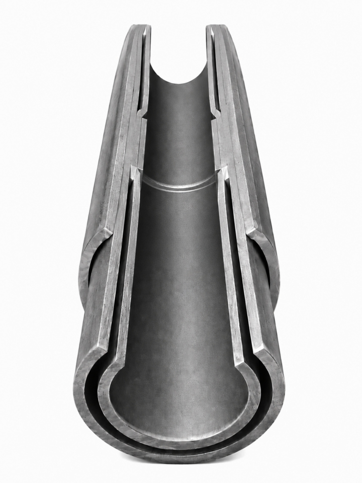
Vacuum Insulated Tubing (VIT)
Thermal barrier solution to save reservoir heat and protect the wellbore
________________________________________
What is VIT and how it works
Vacuum Insulated Tubing (VIT) is a ready-to-install double-walled string in which the inner pipe transports reservoir fluid or heating agent, while the outer pipe provides mechanical protection. The space between them is hermetically welded shut and evacuated, forming a thin thermal insulation layer.
Thanks to the deep vacuum and multi-layer insulation (MLI), convection and heat transfer through gas are virtually eliminated. This makes it possible to maintain the temperature of the transported medium along the entire path from the buttonhole to the wellhead.
Fact: Over a length of 1,524 meters (5,000 ft), VIT loses only about 5.6°C, whereas conventional tubing loses 44°C or more over the same distance. A difference of nearly 8 times.
________________________________________
Why VIT solves real production problems
Heat escaping from the well through the walls of conventional tubing causes a cascade of complications. VIT eliminates the root cause – uncontrolled heat transfer – and therefore its consequences.
Paraffin and asphalted deposition
When oil cools below the crystallization temperature, paraffins precipitate on the pipe walls, narrowing the flow area. VIT keeps the flow temperature above the “cloud point” – costly mechanical and chemical treatments become unnecessary.
Hydrate plugging
In gas and gas-condensate wells, fluid supercooling leads to the formation of methane hydrates. VIT significantly reduces cold start-up time and prevents the risk of hydrate blockage.
Annular pressure buildup (APB)
Heating of fluid in the casing strings by the hot flow inside the tubing causes a dangerous pressure increase. VIT dramatically reduces heat transfer into the annulus, protecting casing integrity and lowering the risk of collapse.
Permafrost thawing
In Arctic fields (such as Yamal, East Siberia), heat transfer from the well into frozen formations leads to thawing and ground subsidence. VIT strictly limits outward heat flow, preventing environmental damage and preserving wellhead stability.
Cyclic steam stimulation (CSS) and SAGD
During steam injection, VIT delivers the heating agent to the reservoir with minimal temperature loss. This results in:
-reduced steam and water consumption,
-lower load on steam generators,
-higher oil production rates,
-reduced operating costs and a smaller carbon footprint.
Viscosity reduction and production increase
Hot fluid flows faster. By maintaining high temperature throughout the entire lift, VIT increases flow velocity and total production without additional energy input.
________________________________________
VIT pipe design
Component | Description |
Inner pipe | Seamless, steel grades J55, N80, L80, P110 (13CrS and other special alloys available). Withstands fluid pressure and medium aggressiveness. |
Outer pipe | Seamless, steel grades J55, N80, L80, P110 (13CrS and other special alloys available). Provides mechanical protection for the insulation and absorbs loads during running and pulling. |
Vacuum annulus | Hermetically welded and evacuated to a deep vacuum. Contains packages of multi-layer insulation and getters to maintain a stable vacuum for decades. |
Premium connections | High-integrity threads integrated with insulated couplings. Heat losses at joints are reduced by more than 95%. |
________________________________________
VIT technical specifications
The table below shows standard sizes and key parameters. Custom manufacturing to individual specifications is available.
Parameter | 7" × 5-1/2" | 5-1/2" × 4-1/2" | 4-1/2" × 3-1/2" | 4-1/2" × 2-7/8" | 3-1/2" × 2-3/8" | 2-7/8" × 1.9" | 1.42" × 0.79" |
OD × ID, mm | 177,8 × 124 | 139,7 × 101,6 | 114,3 × 76,0 | 114,3 × 62,0 | 88,9 × 50,6 | 73,0 × 40,9 | 36 × 17 |
Insulation grade | D | E | C | D | C | D | on request |
Thermal conductivity, W/(m·°C) | 0,006 ≤ D < 0,02 | 0,002 ≤ E < 0,006 | 0,02 ≤ C < 0,04 | 0,006 ≤ D < 0,02 | 0,02 ≤ C < 0,04 | 0,006 ≤ D < 0,02 | – |
Weight, kg/m | 62 | 43 | 32 | 28 | 21 | 15 | 4,8 |
Coupling OD, mm | 200,0 | 160,0 | 133,4 | 133,4 | 108,0 | 88,9 | 50,0– |
Drift diameter, mm | 121,1 | 98,4 | 72,8 | 59,6 | 48,3 | 38,5 | 13,6 |
*Note: Pipe lengths – standard R2 (≈9 m) or R3 (≈12 m); other coupling diameters may be applied upon agreement with the customer.
Pipe steel grades: J55, N80, L80, P110 (special alloys available upon request).